This is part two of a two part writeup on building POE (power over ethernet) devices. This part gathers together the information I discovered when going through this process with the aim to be a useful starting point for others looking to add POE functionality to a device. The previous part covered the design and build of a POE powered and network controlled indicator light.
POE overview and terminology
Power over ethernet allows for devices to be powered over the ethernet cable that is also providing them data. This is achieved by putting a voltage differential between the transmission pairs in the cable which can be extracted by the device. Ethernets data path is magnetically coupled at each end so having the transmission pairs at different potentials does not affect the ethernet interface circuitry.
In POE terminology the receiving end is called the powered device (PD) and the transmitting end is called the power sourcing equipment (PSE). POE has a few methods for referring to how much power can be delivered. On the PSE end devices, capabilities are referred to by a type number or the standard they provide. At the device end there are classes that a PD can report to tell the PSE how much it requires, there isn’t an option for PSEs to restrict to certain classes within a type though. This article will only cover the Type 1 and 2 systems (classes 0-4) as things get more complicated for 802.3.bt. As well as the standardised POE covered here there are some manufacturer specific POE systems and a few variants of passive POE that just add various voltages of power to the cable without negotiation.
| type | name | standard | class | power (from PSE) |
|---|---|---|---|---|
| 1 | POE | 802.3af | 0 | 15.4W | 1 | 4W |
| 2 | 7W | |||
| 3 | 15.4W | |||
| 2 | POE+ | 802.3at | 4 | 30W |
| 3 | POE++ | 802.3bt | 5 | 45W |
| 6 | 60W | |||
| 4 | POE++ | 802.3bt | 7 | 75W |
| 8 | 99W |
There are two connection methods for putting power onto the cable. Mode A (endspan) and Mode B (midspan) both achieve the same goal and powered devices will work with either. The difference is in which pairs the power is delivered over. The differing modes are due to the fact that pre gigabit ethernet only required two data pairs. This made it easier to add power halfway in the unused pairs as you can pass the data pairs through unaltered. As gigabit uses all four pairs this is less relevant now as inline injectors still need to work with lines carrying data.
| pins | 10/100 use | Mode A | Mode B |
|---|---|---|---|
| 1-2 | RX | + | |
| 3-6 | TX | – | |
| 4-5 | + | ||
| 7-8 | – |
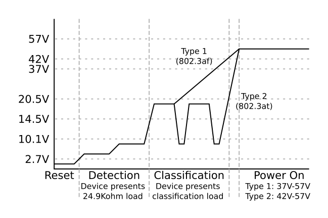
POE performs the detection and classification using the power channel. The PSE initially senses a load resistance in the device then begins the detection process by raising the voltage and measuring the classification current drawn by the device. 802.3at capable sources then indicate their capability to provide this by lowering the voltage, performing another classification, then lowering the voltage again. In both 802.3af and 802.3at the supply then increases the voltage and the device can start drawing power. The PSE will then provide power until the device stops drawing power at which point it will reset and wait to detect the next device, as a result of this there is a minimum current draw of ~10mA in order to remain powered.
An interesting observation is that as POE does all of its setup over the power channel it is possible to just use a POE enabled port for power and not create an ethernet connection.
Equipment needed
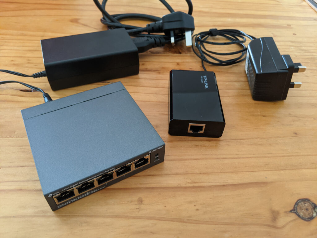
In order to start doing things with POE you will need a source of POE power. Switches designed for business networks will often have model versions with POE, however, these can get pricey. For a less expensive option there are small unmanaged desktop style switches which support POE on a number of ports which are available and are cheaper. In my setup I am using a 5 port TL-SG1005P switch to add POE to my existing network. This has 4 802.at POE+ ports and a non POE port to use as an uplink to the rest of the network. The other option is a POE injector, this adds the power to the cable in-between the switch and device. These are a fairly cost effective option if you want to add POE to a single port but if you need more than one or two ports then a small switch will likely be cheaper. Before adding the switch mentioned previously I used a TL-POE150S injector but this only supports 802.3af.
Circuit design
Now we have covered the fundamentals of POE we can get into the circuitry required to make it work.
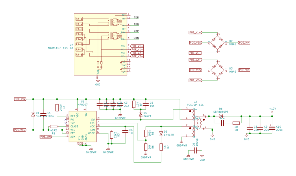
Adding POE starts with the connector. POE requires access to the middle taps of the connector side of the ethernet magnetics. In addition the magnetics need to be able to support the dc current that POE passes through them. These magnetics are available both as discrete modules or integrated into connectors. The connectors and magnetics that support POE will clearly state this so identifying compatible parts is fairly easy.
The next stage is a pair of bridge rectifiers. As the power can appear on any of the four pairs due to the option of mode A and mode B power insertion and the existence of crossover cables (or miswired cables) that can reverse the pairs, the rectifier is required to convert this to consistent positive and negative supply. A pair of standard bridge rectifiers should cover the requirements for this stage.
The next section is the control IC which performs the device side of the detection and classification sequence. These ICs also manage the voltage conversion as well. The device will receive between 37 and 57 volts, this now needs to be converted to the desired voltage for the device to run. This is complicated by the fact that the negative supply voltage provided by the POE supply is unlikely to be at the same potential as the local ground. This is due to a combination of resistance in the return path resulting in a voltage differential compared to the PSE, and the fact that the negative supply at the PSE may not be at ground potential. Due to this the majority of POE devices need to use an isolated power supply design. Devices that don’t have any external electrical connection, or isolate these connections separately, can skip isolating the power supply.
Isolated designs use a transformer to perform the voltage conversion. Some controller ICs like the MP8007 use primary side regulation using a feedback winding on the transformer where as others like the Si3402 use a secondary side voltage monitoring which is reported to the controller via an opto isolator to maintain the isolation boundary. Primary side regulation has a reduced number of components, however, the output voltage control is less stable than secondary side feedback methods, this article goes into more detail on the differences . The transformers used in the reference implementations for the control ICs might be hard to source, however, there are a variety of transformers designed for POE applications that can be swapped in as an alternative, doing so will require selecting a transformer with a roughly similar ratio, many of these transformers give the intended output voltage (e.g. Coilcrafts POExxP series) to make finding the one with the correct ratio easier, then adjusting the feedback resistors to get the correct voltage. For non isolated designs a buck converter can be used, many of the control IC’s will have the ability to operate in this mode. This method can also be made to be isolated by adding an isolated DC-DC converter after the initial stepdown converter.
Once you know what power supply methodolgys are sutiable you can select a controller IC that supports that method, some examples are linked above. The Datasheet of the IC will provide a reference implementation which will provide a solid starting point for the power supply stage, for my design I only needed to adjust the feedback resistors for the different transformer as discussed above.
Conclusion
Hopefully the information above helps you in creating your own POE devices. If I have missed anything Feel free to drop a query in the comments below.
The POE power supply design used in the stack light project discussed in part one can be found in the projects hardware git repo on GitHub.