This is part one of a two part writeup on building POE (power over ethernet) devices. This section covers the design and build of the project, a network controlled stack light, and part two will go into more detail on how to add POE functionality to a device.
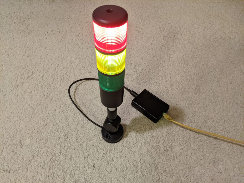
The idea for the project came when I was considering using power over ethernet (POE) for another project and wanted to understand how to implement it in something simpler beforehand. At around the same time I came across the affordable stack light units and thought it would be useful for a few applications so decided to merge the two and build a POE powered version. There are couple of intended uses for the project the first is for status reporting, for things like system availability monitoring, or continuous integration. The other application area is for use in theatrical lighting systems like those used in the Student Robotics competition or for my portable bridge setup for the game Artemis.
Initial Prototyping
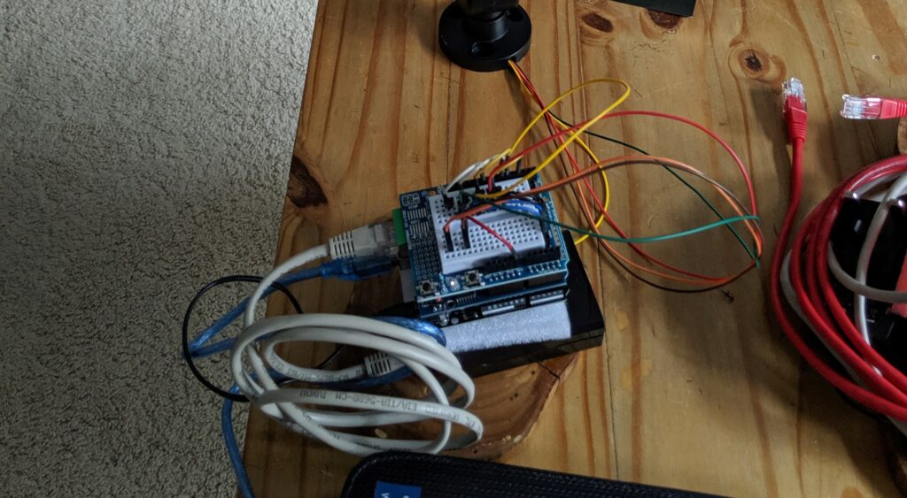
The first iteration was a proof of concept largely consisting of off the shelf blocks. An Arduino with an ethernet shield were used as the control system and powered using A POE splitter. A prototype shield containing the transistors for switching the light was then mounted on top. With this setup the initial firmware was prototyped and got to a functioning state, however, the lack of flash and ram on the chip limited the amount of features that could be enabled at once. The other limitation of this version was that only one segment could be fully lit at a time due to a single current limiter built into the stack light. Despite this the prototype was useful, so development was started on a customised board to control the light.
Initial thoughts were to design the controller to fit into the base of the light. Trying to do this at the same time as fixing the issues with the first prototype proved time consuming and resulted in the project being shelved for a while.
After the hiatus a new plan was created to reduce complexity and get the project moving again by focusing on its core goals. The integrated base idea was scrapped and instead the controller would be placed in an off the shelf enclosure in order to remove the mechanical design aspect of the project and reduce the size constraints on the PCB. The led control was simplified, rather than trying to use a controlled current LED driver, the current limit in the light would instead be duplicated for each channel, this takes more board space, but without the limitation of fitting the design into the base this was no longer an issue. Finally the Arduino based control logic was swapped out with an ESP32 based system as this resolved the processor issues and simplified the network connectivity component of the design.
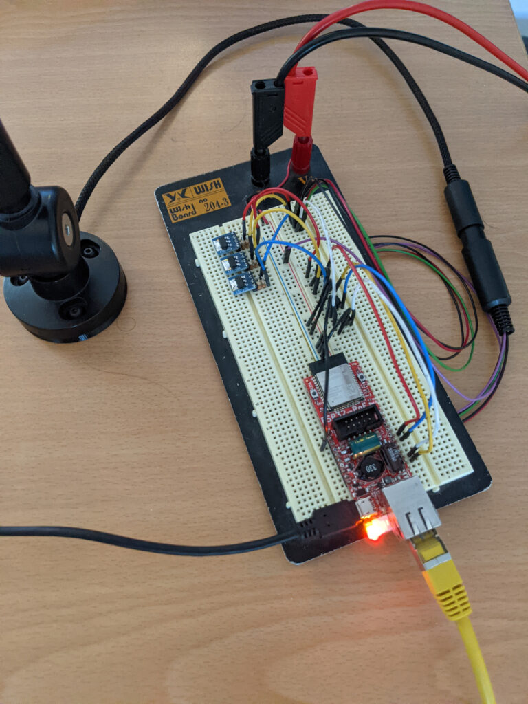
In order to test these plans a simplified breadboard prototype was created with an ESP development board. Unlike the first design which aimed to test the concept, this prototype targeted testing the planned LED control and ESP pinout combination would work before completing the PCB design, as a result the POE functionality was omitted. It also allowed for continued software development while the PCBs were being produced.
Hardware Design
Following on from the second prototype a PCB design was created that merged the required modules together.
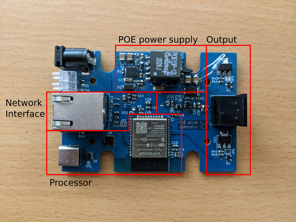
The only major addition from the second prototype was the POE power supply hardware. The design is split into four major sections, the output stage, the POE power supply, the processor, and the network interface.
The stack light takes a common 12v input with switched grounds for each light segment and the buzzer. A mosfet switch was used to control each of the channels with brightness controlled by PWM from the microcontroller. As supplied the light has a voltage regulator based current limiter shared across all the illumination channels, this prevents multiple segments from being lit at full brightness simultaneously. This was resolved by bypassing the current limit inside the light with a jumper wire and then adding a copy of the current limiter circuit in the light to the board for each of the three led channels, giving them their own current limit.
For the POE power input, a transformer setup rather than a switch mode design was used. The use of a transformer based design provides electrical isolation and allows other connections to be exposed without the risk of a short.
The power over ethernet schematic is based on the MP8007 reference design. The catch with many of the reference designs for POE PD controllers is that the transformers used in them are not easily available, therefore, the transformer needed to be replaced with a more easily acquired Coil craft transformer requiring a change to many of the other components as well. A backup DC jack was also added in the event that something was wrong with the POE design.
An integrated ESP32 wireless module was used for the main processor. As the module isn’t needed for its wifi capabilities the ESP32 could have been added as a standalone chip, however, using the module simplifies the design as compared to using the ESP32 IC directly and the extra board space occupied wasn’t an issue. The large voltage drop from the main 12v supply required for the light to the 3.3v supply needed for the control circuitry prevents use of a linear regulator as this would produce quite a lot of heat. Instead a stepdown switch mode power supply was used to provide the 3.3v supply. A USB to serial converter was included to facilitate easy programming and give the option for a serial console interface if wanted.
The network interface uses the LAN8710A ethernet transceiver IC. This communicates to the ESP32 with the RMII protocol used for 100MB ethernet PHYs. In order to support the POE functionality an ethernet connector with internal magnetics that expose the centre taps of the cable side of the interface was chosen.
With the design sorted the PCB could be laid out. The PCB was designed to fit into an off the shelf enclosure in order to minimise the mechanical complexity of the project. The design has several SMT components with underside ground pads so large vias were added under each of these ICS to give access to these pads and enable hand soldering of the board. Other than that it was a fairly standard PCB creation process.
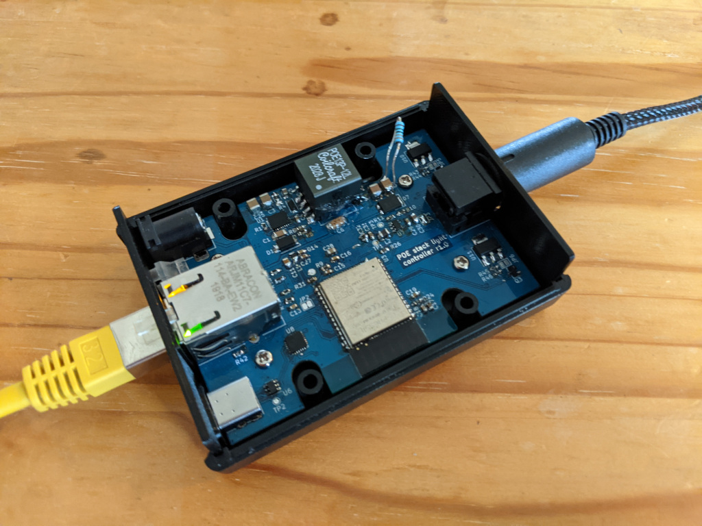
Once the boards arrived and the first unit assembled a couple of issues were discovered. The most problematic was that the POE transformer output was reversed which was fixed by soldering wires to the correct locations. In addition the ESP32 and control circuitry draws less power than the minimum required for the POE power source to continue supplying power so an additional load resistor was added to draw the required power. The other notable problem is that the POE transformer has a high pitched wine when at low power which has yet to be solved. The board was otherwise functioning and worked with the firmware that has been used on the second prototype.
Software
The software was created with two control methods, one for use with theatrical lighting systems and the other for use with other systems. these modules then controlled the hardware through a shared set of hardware management modules.
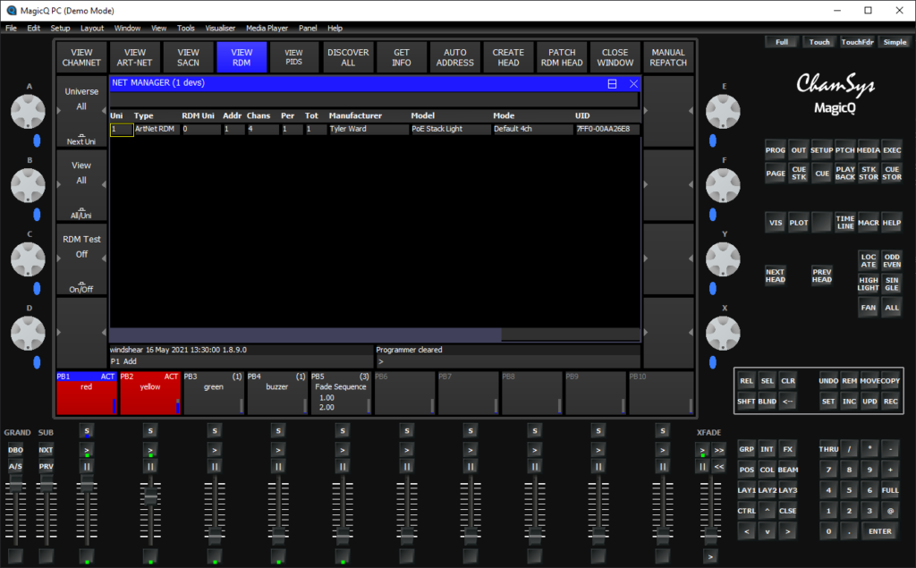
Theatrical lighting systems use the DMX protocol to control lights. DMX transmits 512 channels of data that control aspects of lighting fixtures. DMX is usually sent over dedicated cables but can be sent over a network using the Art-Net protocol. Within a DMX universe, lights can be detected and configured using the RDM protocol. While RDM is an optional component of DMX, adding support for this allows lighting consoles to automatically detect or edit the lights configuration, such as which channels within the DMX datastream it should use, without needing to use another configuration method.
For both Art-Net and RDM the protocols are published publicly and simple enough that they can be implemented from scratch, which is useful as there were no premade libraries that looked suitable. The basic implementation of these was created with the first prototype and refined through the later prototypes. The Art-Net and RDM code blocks were also designed so that they could be reused later in a different project without needing to rewrite much of the code. The stack light is setup to use four DMX channels, one for setting the brightness of each of the three light segments and one for the buzzer.
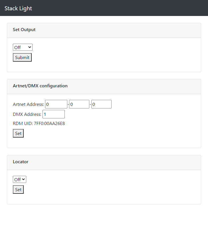
For use with things like status monitoring tools and to provide a user friendly configuration interface a web interface was used. The ESP32 has a good amount of available flash so a bootstrap template was used to create the user interface in order to provide a fairly nice looking user interface. A combination of static files and templated files were used to create the webpage. There isn’t a templating library for the ESP32 so I created a basic one which replaces tags in the saved file with strings calculated by a separate function. Settings are set from the webpage via a series of API endpoints which accept post requests with the new settings and update the configuration as required.
With these interfaces functional, the stack light is ready to be put to use. While writing the firmware I identified several future feature additions that could be added to improve the lights functionality. To avoid the project ending up in a state of continual feature creep these have been added to the issues list and marked as potential enhancements that can be added in the future if they become useful.
Conclusion
The final steps in completing this project was to writeup some documentation and create archives of the project build outputs. By documenting the build steps and project components it makes it easier for other people or myself to build in the future and allows for easier reuse of parts of the project when building other systems. Archiving the outputs from when building a project is also useful both for ease of others building the project but also as it allows for a project to be built even if components required to build the project (e.g. development tools) are for some reason unavailable or incompatible in the future. The project is open source and the designs and documentation can be found at the github repositories listed below, along with downloads of the compiled firmware and board manufacturing files. The project artifacts can also be found on the projets Hackaday.io page.
Hey ,
Just impressed by your electronic projects on your blog!
Really looking forward to see your plan comes true and go further.
I’m Wendy,the marketing guy from a PCB manufacturer in
China.
We would like to support you to finish the project with providing free PCB
board or maybe cooperate in other terms you may interested in.
Hope to get your reply.
Hi Wendy
Thanks for getting in touch, and glad your are enjoing the projects. Thanks for your kind offer, while this project is completed I am also working on other electronics projects which will eventualy need PCBs (not sure when as my time to work on these projects can be quite unpredictable) so will reach out when I get to that stage on them.
Thanks
Tyler
Hi Tyler, I’m also keen to follow the progress you’re making on this project. In particular I’m in need of some inexpensive PoE LED drivers for domestic use that are capable of delivering the full 802.3at 30W rating and drive up to five (5) outputs – principally RGBWwWc strings.
However a major blocker issue would be the high pitched PoE transformer whine you report experiencing at low power. Is this an issue you’ve managed solve yet?
Also would you be able to reveal the quiescent power drain of the whole device, including stacklight, when the LEDs are fully switched off?
Hi Dion
Sounds like an interesting project. The POE IC I used in this project is only designed for the af spec at 15w however there is a good range of ICs out there that are able to deliver 30w.
I believe the issue I had with the transformer wine is not an uncommon issue with primary side regulation transformer circuits. I heavily reduced the noise when I built some more units by adding some more load resistors to increase the power draw, with this change I can only hear the whine when I put my ear very close to the device ~10cm but it will use more power at idle. Using another voltage conversion method e.g. secondary side regulation will likely avoid the noise. I am thinking of using secondary side regulation for my next POE project for this reason.
I have checked the POE power draw of the original unit and the switch is reporting 1.2w (of which ~0.4w + conversion losses is the load resistor in that one) when the lights are off. The one with the extra load isn’t on a managed switch so I don’t have a value for that one but would expect it to be about 0.7w + conversion losses higher due to the extra load resistors.
Thanks
Tyler