The new Type-C USB connector is the latest addition to the USB connector standards. It offers reversible plugs, direction independent cables, USB3.1 speeds, and 3A charging in a connector only a little bigger than the USB 2.0 MicroB connector. In order to add these capabilities the plugs and connectors have additional configuration pins to allow devices to negotiate their state. Supporting the configuration channel may seem like a difficult challenge but it can be achieved fairly simply for the basic use cases.
Type-C as a 2.0 device with a type-C receptacle
In this mode the Type-C device is acting as an UFP (Upstream facing port).
This is the equivalent of devices equipped with either a B, Mini-B or Micro-B socket and majority of hobbyist projects will probably fit into this category.
Luckily this is fairly easy to implement as we can avoid worrying about multiplexing or managing connection states.
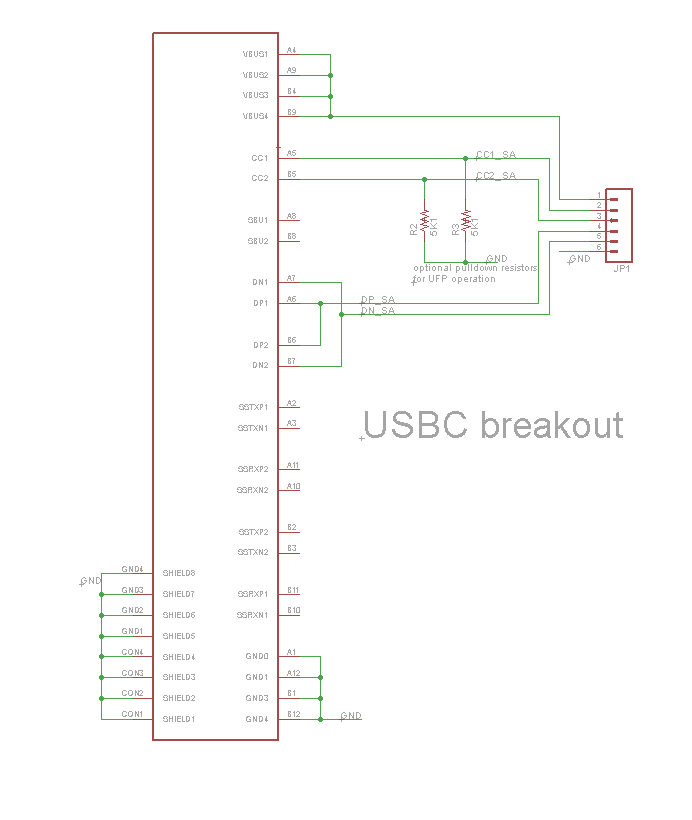
The simplest implementation of this is to use two 5.1k pull down resistors on the CC lines.
This allows for detection by other devices when using a USB C-C cable.
The USB 2.0 Data lines can both be connected together at the receptacle as only one pair will be populated in the connector.
The power and ground lines will all want connecting to the appropriate power rails on your board.
The Sideband pins and superspeed pins should be left unconnected in this configuration.
Type-C as a 2.0 device with a type-C plug or captive cable
If you wish to have a device plug directly into a Type-C receptacle this can be done much the same as above with a few small differences.
As the orientation of the plug is fixed at your end only one pull-down configuration resistor (5.1k) will be needed (the one attached to A5). This needs to be the correct cc channel as some devices multiplex the USB2.0 data lines.
In addition only one set of USB 2 data pins should be present in the plug (A6 and A7) so there isn’t a need to connect to both pairs like the previous case.
Using Type-C power on devices
If you want to use Type-C power which provides up to 3A at 5V (note: this is different to the USB Power Delivery capabilities) you will need to monitor the voltages at the CC lines to perform power detection. This can be achieved by either using an ADC to measure the CC lines (or using a IC such as the one discussed further down to manage the CC detection for you). Table 4-36 in the USB Spec (version 2.0) covers the voltages that represent the power sources capabilities. note: the capabilities of a host may change while connected so this needs to be monitored throughout the connection.
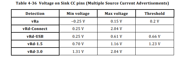
This can be simplified into the folowing states of a CC line
- less than 0.2v nothing is plugged in/the other CC line is connected.
- between 0.2v and 0.66v only default USB power is available.
- between 0.66v and 1.23v 1.5A USB-C power is available.
- above 1.23v 3.0A USB-C power is available.
note: there are many out of spec legacy cables available that have the wrong CC pull-up resistor, this leads them to advertising the wrong power capabilities of the charger or host.
Type-C as a 2.0 host or dual role device.
Using Type-C as a DFP (downstream facing port) or a DRP (dual role port) is a bit more complicated than the previous example.
This is because the host needs to detect the connection before connecting VBUS to the device.
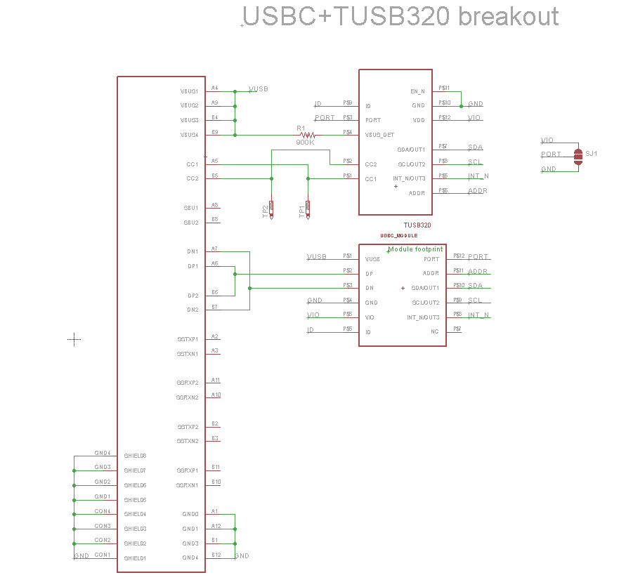
While it would be possible to do this yourself there are configuration channel control ICs available to perform this task such as the TUSB320.
These ICs handle the majority of the work for you.
The bits you are left with are turning on VBUS once connection has been established and putting your device into the correct USB mode.
This is often already provided by your controller if it supports USB on-the-go, many configuration ICs have an ID pin that acts like the ID pin on on the go connector for this reason.
Even if you are using the device in host only mode, you will need to enable VBUS only when a connection has been established to prevent two USB devices attempting to provide power at the same time.
An example schematic using the TUSB320 is shown below.
USB 3.1 operation and USB Power Delivery
While USB3.1 superspeed multiplexing and USB power delivery are outside of the scope of this guide there are ICs available which provide these functionalities however they are often in BGA packages which are difficult to work with.
References
- USB Type-C Specification v2.0
- Benson Leung – Resistors in legacy cables
- Schematic and board files
- Hacaday.io Project
Updates
- 2019/11/09: Clarified Type C current section and fixed references as table number have changed in newer specification versions
Pingback: DIY USB Type C | Hackaday
Hi Tyler!
Great guide! One quick minor correction I noticed in your description of Type-C UFPs.
“The simplest implementation of this is to use two 56k pull down resistors on the CC lines.
This allows for detection by other devices when using a USB C-C cable.”
The Rd pulldown should be a 5.1kΩ resistor. The schematic looks correct though with a 5K1 resistor. Otherwise, thanks for posting this! It should be invaluable for hobbyists looking to use Type-C in their designs!
Benson
Hi Benson
Thanks for spotting that, I have updated the article
Tyler
Pingback: Using USB Type-C on hobbyist projects - Electronics-Lab
Hi! I’m still new at electronics tinkering and would like any help you could give me on USB C. I want to make a custom PiHat that would allow me to add at least one usb type c to my raspberry pi. I’d also like to be able to make my own alternate mode (if possible) that would essentially allow me to access the pi’s gpio. Thank you in advance.
Hi Bryan
I haven’t used any alternate modes myself, Devices discover and setup alternate modes using the USB PD spec which I have yet to play around with.
There is an open source Google project that implements the display port alternate mode that might be able to help.
https://www.chromium.org/chromium-os/dingdong
Tyler
Thank you so much!
Hi! Thanks for posting this!
Where on the USB 2.0 side should the CC1 and CC2 lines connect? That is a bit unclear from the JP1 representation.
Trying to use this to add a USB-C plug to a microcontroller.
Hi Henri
If you are just building a usb 2.0 device with a Type-C connector you only need the pull down resistors and don’t need to connect the CC lines to anything else. However you may wish to connect these lines to other circuitry in order to sense if Type C power is available hence why they are connected to JP1 in the breakout board.
Hi!
Sorry for being a total jackass here but could you please assist me with something that I can’t figure out?
If I want to convert a micro USB port to USB C ( for a DIY project of mine).
How should i wire it up to be able to use the USB 2.0 device both with a USB type A (Master) > USB-C (Slave) and USB C (Master) > USB C (Slave)?
In other words, I want it to be compatible with both my desktop PC (USB A) and my laptop (USB C).
Kind regards,
Jonathan
Hi Jonathan
You will want to have a type C receptacle on your device with the two pull down resistors. See the “Type-C as a 2.0 device with a type-C receptacle” section for a schematic and details.
You can then use an A-C cable when using it with your desktop and a C-C cable when using with your laptop.
Hope that helps
Tyler
Hi, I’m having some issues when I follow the instructions for “Type-C as a 2.0 device with a type-C receptacle.” I’ve wired it up how the schematic shows (using 4.7kOhm resistors instead of 5.1k), yet when I plug it in to windows 10 I get an error saying “the last USB device you plugged into this computer malfunctioned…”
I’ve checked my wiring many times, and still have had no luck with getting it to work. I’m trying to put a USB C connector an an Arduino Nano.
Any help would be greatly appreciated!
-Alex
Hi Alex
I have had that error a few times on windows, I have seen it when there is a connection problem with the USB data lines or configuration on the microcontroler such as a bad USB descriptor.
Some things that you could help in debugging it.
Check for signal continuity through the connector and that the data lines aren’t shorted to anything else (the C connectors are quite fine pitch so this can happen fairly easily) I tend to use a USb breakout on the end of a cable for testing but you can get a multimeter probe into a USB A connector if you don’t have a breakout to hand.
Try using a USB 2.0 A-C cable if you are using a C-C cable as this will allow you to check if the basic USB functionality is the issue or if it is a problem with the type C detection or the usb 3 pins.
In the case of USB descriptor problems I have found the linux lsusb command or the USBView utility from Microsoft to be useful in checking if it is a low level signal problem or a problem with the device firmware, usually devices with signal problems wont enumerate atall.
I hope that is useful in getting it fixed.
Tyler
Hey Tyler, I wanted to use your diagrams to convert a micro USB teensy to USB-C (as an UFP).
You used to have great wiring diagrams, any chance you still have them somewhere ?
Many thanks !
Hi Quentin
Apologies for this, looks like they got misplaced during the server move, they are back up now, glad they are usefull.
Thanks
Tyler
Hey.
The images in the post have seem to become 404
Thank you for posting this! I would like to power a dumb device from a USB-C port and I only need 500mA @5V (USB 2.0 default power). Do I need to do anything more than the pair of 5.1k pull downs on the CC pins to keep the power flowing from the source?
Hi Matt
That is correct, for a minimal power only implementation as long as you have the cc puldown resistors then you will be able to get power from an upstream device
Hi, Tyler.
Sorry to dig up this older article, but I’m struggling a little. I’m making an adapter to power a device that requires 5V and can draw up to 3A. The adapter will simply have a USB C receptacle to use a charger as the source of power. If I understand it correctly, placing a 5.1K pull down resistor on both CC1 and CC2 will make the adapter look like a USB 2.0 device and, i think, only make 500mA available. What do I need to do on the adapter (USB C receptacle) end to ensure 3A @ 5V is made available by the charger?
Thanks,
oz
Hi Oz
The pulldown resistors indicate to an upstream device that a client is connected and will be the same regardless how much power a device uses. Chargers or USB-C host devices instead indicate the amount of power they can provide using differing pullup resistors on the other end of the CC lines. To detect the capabilities of the carger you will need to sense the voltage on the CC pins. I have updated the section above on Type-C current detection to include the table from the specification (the table number has changed in recent versions so no longer linked to the correct one) which shows what voltages are present on the CC pin for each current capability. Once you have sensed the CC lines you can tell what current is avaliable from the port and how much power you are able to draw. You might be connected to a device which can’t supply 3A type-C current, your options when this happens are to either run at a lower power level or only fully power on if the full 3A is avaliable.
Hope that helps
Tyler
Tyler,
That makes so much sense. I basically had the responsibility flipped. It was starting to dawn on me as I continued to poke around that it was up to the device to not draw more current than it should. I would like to make a responsible device that doesn’t turn on unless it senses it can draw up to 3A. Do you have any recommendations for ICs that can handle that detection? Maybe I’ll break out LTSpice and figure out how to toggle my power protection chip’s enable pin using basic components… My EE skills are rusty.
Thanks,
oz
Just re-read the post. TUSB320! Time to read some datasheets.
Thanks for all your help!
oz
As well as chips like the TUSB320 (combined with an external logic gate) you can also use a pair of analogue input pins on a microcontroller to read the values from the CC lines and then control your power supplies enable pin. Using more basic components a pair of analogue comparators and logic to connect their outputs would also work, but the other options are easier to do.
So, if I understand you right, if I just add a TUSB320 and the proper resistors on the CC lines I can convert my USB 2.0 device (let’s say, a custom keyboard full of the LEDs the kids likes these days) to Type C connector and draw up to 3A, without any additional circuitry and mess with PD? Is that right? If so, I have a use case that could benefit from that.
Thank you for this post!
HI Vinny
The device will need to confirm that the port it is connected to can provide 3A before it draws it (not all type C ports are ale to provide 3A). but this can be done without needing power delivery by checking the pullups on the host end, chips like the TUS320 can do this or you can do it yourself using a pair of ADC pins.
Is there a PCB Layout available for the tusb320 breakout.
The PCB designs and schematics for the boards in the article can be found at https://github.com/Tyler-Ward/breakouts. They are on a combined board with some other breakouts I needed at the time but should be able to be seperated out fairly easily if you just want the tusb one.
Hi Tyler,
I’m trying to power a Fire HD tablet (using its USB C port) with a 5VDC supply *and* enable serial comms with an Arduino connected to the same port (that would also be powered with the same supply.) Trying various different cables and DIY solder USB C boards I can get either power to the Fire and Arduino *or* serial comms working. Haven’t been able to get both working. Do you know if a simple resistor combination will work, or if the TUS320 is the only way….or perhaps this isn’t even possible?
Thanks!
Hi Pascal
There isnt an easy way to do this with USB-C. It is supported via the role swap feature in usb power delivery, this requires both ends of the link to support power delivery and then to request a role swap. The TUSB320 doesent support power delivery commands so you would need a different chip to manage that and likley some software to mange that chip.
Your best bet might be to try integrating/canabalising a chargethrough style typeC hub as these use the above method to achieve the chargeback functionality. This still relies on the tablet supporting this functionality however.
Great article Tyler, thanks for all the support you give.
Regarding CC pull-up/pull-down: OnSemi have a great app note on protecting your UFP from some CC (badly?) configured cables, by using zener diodes:
https://www.onsemi.com/pub/collateral/an-6102.pdf
I am concerned that an illegal cable or some other cable my customers may use could present high voltages on the Vbus of my UFP, which is just a dumb port to provide 5V max. and the minimum 500mA, so:
– is the 5.5K Rd pull-down all I need to do (and perhaps these zeners) to cast-iron guarantee the Vbus will not exceed 5V with any good/bad cables out there?
Hi Tim
That document is covering how to add protection for when using the fast charging standards that worked over usb A ports. All of those protocols I have encountered required the device being powered to indicate that they want the increased voltage, often by applying specific voltages to the data pins. Those protocols will have been designed to prevent acidental activation due to the risk of damage to other devices if the vbus voltage is increased. Therefore you shouldn’t need to do anything to avoid being provided with more than 5v, a faulty usb supply could still provide more than 5v but would also break most other devices plugged into it. If you want to add extra protection e.g. it is used in an industrial setting you could add an over voltage protection circuit to the vbus and data inputs along with the zenners recomended in that guide.
Hi Tyler,
Apologies for bringing back an old article, but I’m having some trouble. I want to change my mouse’s charging port and data transfer from a micro b v2.0 connector to a type-c v2.0 connector. My aim is to solder a flex PCB on top of the existing circuit board, but I’m not sure what to do with CC1 and 2 and if I can match the pins as follows after sketching a ‘Type-C as a 2.0 device with a Type-C receptacle’ schematic: VBUS to VCC, D- to D-, D+ to D+, and Gnd to Gnd or not. I appreciate any advice or direction on this subject and any other issues I should keep in mind before making this change. Thank you for your assistance!
Hi Billy
Sounds like an interesting project.
The power and data connections on your mouse will want to be connected to the connector pins with the same name as in your message (dont forget to connect up both of the USB 2 data pairs (one for each orientation) should your connector not join them internaly). For the CC pins you will want to add a 5.1K pulldown resistor to Gnd on each of them, this allows a usb host port to detect the mouse as a client when it checks the state of the CC line. As your mouse doesent need to read the CC pins (due to it not having any need of the higher current modes or orientation detection) the CC pins wont need to be connected anywhere else.
Hopefully that will have make things clearer, but feel free to ask if anything above is unclear.
Tyler