The new pi has been released and it has a USB Type-C connector for power however people are finding some chargers are not working with it (notably macbook chargers). Some have speculated that this is due to a manufacturer limitation on the power supplies however it is actually due to the incorrect detection circuitry on the Pi end of the USB connection.
For those looking for a solution for the problem and and aren’t interested in the technical details a set of potential solutions are given at the end of this post. The newer version of the pi 4 has altered its USB-Type C connector alowing it to work with emarked cables.
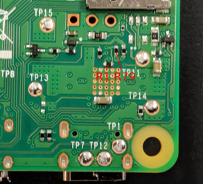
The root cause of the problem is the shared cc pull down resistor on the USB Type-C connector. looking at the reduced pi schematics we can see it as R79 which connects to both the CC lines in the connector.
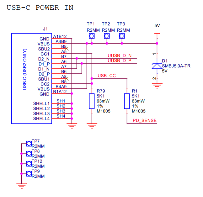
With most chargers this wont be an issue as basic cables only use one CC line which is connected through the cable and as a result the pi will be detected correctly and receive power. The problem comes in with e-marked cables which use both CC connections. To understand this lets look at the Type C specification document.
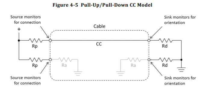
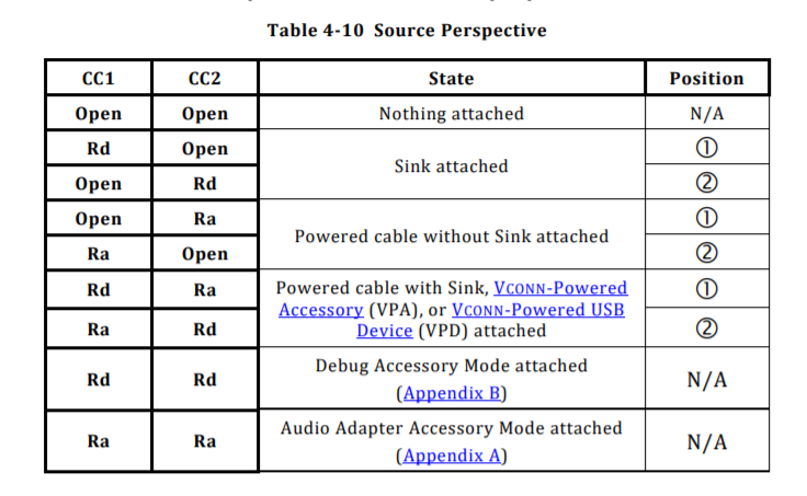
Per the spec the source device doesn’t provide power on the connector until it detects a sink device being attached. which is done by the presence of the Rd resistor (5.1K ohms) to ground. Active cables also signal their presence using another value or resistor Ra (800 ohms – 1200 ohms). The Type-C specification has a table for looking up what is connected based on the state of the CC lines.
Excerpt from the Type-C spec (Figure 4-10)
In the correct operation the charger will sense the Rd resistor (Or Rd Ra cobination) and turn on the power. The problem comes when an active cable which presents an Ra at both ends is used. On the source side one CC pin will be connected to the Ra resistor in the cable and the other to the CC line to the Pi. The Pi has connected both lines together so presents the combination of the Ra at the pi end of the cable and the Rd pulldown. Calculating the presented resistance assuming a average value of Ra still gives a value well within the Ra range (also note Ra resistances are permitted to go below 800 when cable electronics are drawing power so a resistance lower than 800 will also likely be detected as Ra).
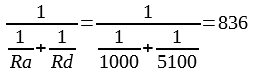
Pi’s presented resistance
With effectively two Ra values presented to the Source end it will detect the Pi as an “Audio Adaptor Accessory”. These are analogue audio interfaces to allow for headphones to be connected to phones for example (although some phones use headphones/adaptors with inbuilt sound-cards which appear as USB devices). The audio adaptor accessory also allows the phone to be charged through the adaptor. This means the the device should not provide power on the Vbus pins which means no power for the Pi.
In order to test this I attempted to power the pi with a macbook charger and its e-marked cable and it didn’t receive power. Two other chargers (a pixel 3 charger and an office electrics desk charger) where tested with the macbooks active cable and none powered the pi. When tested with a couple of non e-marked cables the pi was powered by all the chargers. This lines up with what is expected.
With regards to manufacturer limitations it is possible for chargers and devices to limit which devices they will use however this is only applicable for power deliver modes (higher voltages and currents) as the basic detection doesn’t give scope for such communication to occur.
While this write-up focuses on units with detachable e marked cables as this has a clear set of detection steps when the CC lines are shorted. the problem could also happen with integrated cables if they are interfacing with both CC lines and dislike them being connected.
Now onto some solutions. Assuming the issue you are having is caused by the problem discussed above, using a non e-marked cable (most USB-C phone charger cables are likely this type) rather than an e-marked cable (many laptop charger/thunderbolt cables and any 5A capable cable will be in this category) will allow for the pi to be powered. In addition using older chargers with A-C cables or micro B to C adaptors will also work if they provide enough power as these don’t require CC detection to provide power. Ultimately though the best solution in the long run will be for there to be a board revision for the pi 4 which adds the 2nd CC resistor and fixes the problem.
In conclusion. If you want your USB Type-C devices to work correctly then you need to have two independent CC resistors. If you are interested in adding Type-C connector to your project and don’t want to read the whole spec to do so I have previously written a guide on how to do so.
Since this was published Eben Upton from the Raspberry pi foundation has commented that he expects this will be fixed in a future board revision in comments reported on Techrepublic, no word yet on timings on the release of this revision though.
updates
* 2019/06/28: Added additional information on solutions.
* 2019/07/04: Added test results and checked details on a pi.
* 2019/07/08: Added link to conformation from raspberry pi foundation
* 2020/03/24: Added information on newer model.
Another possible issue can occur in use of USB type-c to USB type-c extension cable (with wires on both cc lines) to connect with dual role capability device (hubs, laptops, etc).
Pingback: Lilbits 372: Raspberry Pi 4 charging issues (and USB-C confusion) - Liliputing
So just cut the trace between CC1 and CC2, and solder another 5k1 between whichever doesn’t have it and ground, right?
While that will work in theory the trace linking the cc lines appears to be under the connector which would make this a challenging soldering task.
Minor typo “When tested with a non a couple of non e-marked cables the pi was powered by all the chargers.”
Thanks for spotting, have now corrected
On a related note, is the Pi 4 supposed to read the 56k Pull up resistors on legacy USB A/USB-C cables? I tried one without data lines and I was able to pull as much current as I needed. Is this also also an error?
Is the Pi 4 not negotiating current like previous models?
The Combined CC connection is connected to the analogue input on the power supply IC but im not sure if it is being used to determine how much power to draw.
Did you hear anything back from the RasPi team? Would they redesign?
I haven’t heard back directly however there has been an official response which has been reported at https://www.techrepublic.com/article/your-new-raspberry-pi-4-wont-power-on-usb-c-cable-problem-now-officially-confirmed/
Pingback: Raspberry Pi admits to faulty USB-C design on the Pi 4 | Ars Technica
If you want to make a source, what is the proper value for Rp? I’m having trouble finding that…
The value of Rp depends on what current the power supply can provide. In the USB-C spec it can be found in Table 4-24 which has values for pullups to both 3.3 and 5v as well as current sources. For a pullup to 5v the values are as follows 56k for default USB power, 22k for 1.5A and 10k for 3A.
what about just cutting the trace from either cc1 or cc2 to ground on the 4Pi board? Does that put it into State “sink attached” (cc1 open, cc2 Rd)?
The trace connecting the CC pins is under the connector making accessing it quite difficult, however if it was cut then the pi would only be detected with the cable in one orientation as only one of the cc lines will have the identification pull-down.
understood, thanks!
i’m mainly thinking about someone who wants/needs to use usbC with an e-marked cable (lets call that usbCe), such as if they’ve already purchased it for use with the 4Pi, or if that’s all they have on-hand. if they use the Pi like i do, i almost never remove the power connector, so once it’s in and working, it’d be fine.
i’ll have to look at the usbCe connector on the 4Pi more closely, but maybe rather than trace-cutting, a pin in the connector could be cut, removed, or painted over for the same effect, without harming the usbCe cable/power source. separately, an add-on dongle could work (though, at the prices were talking about, it’d have to be REALLY inexpensive to be a viable option).
it looks like those pins are accessible from the back of the header and can be clipped/cut. see really cool radiograph of the 4Pi:
https://www.raspberrypi.org/app/uploads/2019/07/gtW8Qws.jpg
ooh. this one is even better. it focuses directly on the usb-c header:
https://i.imgur.com/HlRV90U.jpg
Pingback: The Raspberry Pi Foundation messed up its first USB-C device - The Verge
Pingback: Confirmed: Raspberry Pi 4 suffers from significant USB-C design flaw
Tyler, in what kind of time frame you think might be realistic to expect revision of the board with the fix?
Great explanation. Raspberry Pi cofounder Eben Upton told TechRepublic the issue will be fixed in a future board revision. Before then, using Raspberry Pi 4’s would be the best way to go.
Pingback: Pi 4 with partial USB Type-C fixes – The blog of Tyler Ward (aka scorpia)
Great write up! Thank you for the understanding
Pingback: USB-C Power Issues With Development Boards | Robert Lipe on Technology